Capacitors: Selection Criteria and Application Examples
- Lentark Electronics

- Dec 18, 2020
- 11 min read
Updated: Jun 12

Capacitor Selection Overview
Capacitors are used in almost every area of electronics. Although their basic operating principle is the same, they can perform many different functions depending on the circuit structure, signal type, frequency range, voltage level, and energy requirement.
For this reason, capacitor selection is an important part of electronic circuit design. Selecting the correct capacitor type requires understanding both the electrical requirements of the application and the function that the capacitor is expected to perform in the circuit.
Each capacitor family has its own strengths and limitations. A capacitor that performs well in one application may not be suitable for another. Therefore, capacitance value alone is not enough for proper selection. Rated voltage, tolerance, ESR, leakage current, frequency response, ripple current capability, dielectric material, temperature stability, and physical size should also be evaluated.

1. Main Functions of Capacitors
Capacitors have many electrical and physical parameters, including capacitance value, package size, tolerance, rated voltage, operating temperature range, temperature stability, voltage stability, pulse current capability, leakage current, and equivalent series resistance.
Different capacitor types perform better in different parameters. For example, one capacitor type may be preferred because of its small physical size, while another may be preferred because of its stable capacitance under applied voltage. However, a capacitor type that provides an advantage in one parameter may create a disadvantage in another.
For this reason, the function of each capacitor in the circuit should be understood clearly before selecting the capacitor type.
In a general sense, capacitors are commonly used for two basic functions:
coupling,
decoupling or bypassing.
However, even within these two basic categories, the required capacitor characteristics may vary significantly. The impedance of the connected lines, voltage levels, noise level, frequency content, signal amplitude, and expected current capability all affect capacitor selection.
For example, a decoupling capacitor placed near the supply pin of a microcontroller and a capacitor connected to the switching output of a DC-DC converter both perform decoupling-related functions. However, the required capacitor characteristics may be very different in these two cases.
Understanding the differences between capacitor types helps the designer select the correct component and allows the capacitor to perform its intended function more effectively in the application.
1.1. Coupling Applications
Coupling capacitors are used to transfer an AC signal from one circuit section to another while blocking the DC component between them. In other words, a coupling capacitor connects two circuit paths in terms of changing voltage while preventing a direct DC connection between their bias points.

When the voltage applied to a capacitor changes, the voltage across the capacitor cannot change instantly in a real circuit. A certain amount of time is required for the capacitor to charge or discharge. This behavior is determined by the capacitance value, the impedance of the surrounding circuit, and the available current path.
If the energy source, transmission path, and capacitor were ideal, the voltage across the internal plates of the capacitor would immediately follow the applied voltage. In practice, this would require infinite current during charging or discharging, which is impossible in a real circuit.
For this reason, the charge and discharge behavior of the coupling capacitor should be considered during selection.
When the voltage on one side of the coupling capacitor changes, charge redistribution occurs through the capacitor and creates a corresponding signal on the other side. If the second side is connected to a high-impedance input, the charge/discharge behavior may be slower and the signal response may be shaped by the input impedance and the capacitance value.
Coupling capacitors are used in applications where the voltage change on a signal path is more important than the static DC voltage between two nodes. Audio signal processing and RF signal processing are common examples.
In many signal-processing applications, one side of the coupling capacitor is connected to the signal line, and the other side is connected to a high-impedance amplifier input. Additional filtering or offset voltage may also be applied if needed. This allows the desired AC signal to be transferred, amplified, or shifted to a different operating voltage range.
A coupling capacitor does not pass the signal perfectly. It behaves together with the surrounding circuit impedance and forms a frequency-dependent transfer path. For this reason, low-loss and low-impedance capacitor types are generally preferred when signal deformation should be minimized. However, in some applications, intentional attenuation or filtering may also be part of the design.
Table 1: Important parameters to consider when using coupling capacitors.
Parameter | Notes |
Rated voltage | The rated voltage should be higher than the maximum voltage that may appear across the capacitor during operation. In capacitor types where capacitance changes significantly with applied voltage, such as Class 2 MLCCs, choosing a higher voltage rating can improve stability. |
Capacitance value | A coupling capacitor behaves as part of a high-pass filter. The capacitance value should be high enough to pass the desired signal with acceptable loss, but low enough to block unnecessary low-frequency variations when required. |
Tolerance | Low-tolerance capacitors should be preferred when the exact capacitance value directly affects circuit performance. |
Dielectric material | The dielectric material affects frequency response, leakage current, stability, and losses. For example, electrolytic capacitors generally have limited high-frequency performance and higher leakage current. |
1.2. Decoupling and Bypass Applications
Decoupling capacitors are used to suppress voltage fluctuations on a line. They are commonly used on power lines, DC nodes, PCB signal inputs, local supply pins, and noise-sensitive circuit regions.
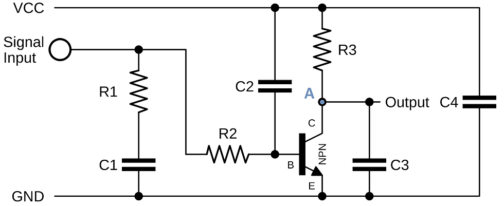
The capacitors shown in Figure 3 all perform decoupling-related functions. Unlike coupling capacitors, at least one terminal of a decoupling capacitor is usually connected to a low-impedance node. This node is commonly a power or ground line where charge can be exchanged quickly.
A decoupling capacitor must have sufficient rated voltage to withstand the voltage on the connected line. It should also have sufficient instantaneous current capability to absorb or supply the transient current associated with voltage fluctuations.
The required current capability may be very different depending on the circuit location. In Figure 3, the difference between C3 and C4 can be used as a practical example. When the transistor is in the off state, point A is pulled up toward VCC through R3. In this condition, both C3 and C4 may appear to be connected across similar voltage levels. However, the energy associated with the voltage fluctuation at point A is limited by R3. Therefore, C3 can suppress this local fluctuation with a relatively lower instantaneous current requirement.
C4, on the other hand, is connected directly across the main supply line. If a voltage fluctuation occurs on this line, there may be no series resistance comparable to R3 to limit the transient energy. For this reason, C4 must be selected with a higher pulse current or ripple current capability than small-signal decoupling capacitors such as C1, C2, or C3. In this type of high-current decoupling position, capacitor types with limited ripple current capability may not be suitable.
When decoupling is created using a capacitor together with a resistor, such as C1-R1, C2-R2, or C3-R3 in Figure 3, the time constant of the RC network should also be considered. The resistor limits current and forms an RC network with the capacitor. This determines how quickly the circuit responds to voltage changes and how effectively it suppresses unwanted signal components.
For example, R3 provides the collector load impedance of the transistor, while C3 helps prevent the switching-related signal at point A from coupling back into the supply line. In this case, the time constant should be selected according to the switching behavior of the transistor so that C3 can perform its decoupling function effectively.
In decoupling applications, the capacitor should be selected according to the frequency range that must be suppressed, the acceptable voltage ripple, the impedance of the circuit, and the expected transient or ripple current level.
Table 2: Important parameters to consider when using decoupling capacitors.
Parameter | Notes |
Rated voltage | The rated voltage should be higher than the maximum voltage that may appear across the capacitor. For capacitor types whose capacitance decreases under applied voltage, selecting a higher voltage rating can improve circuit stability. |
Capacitance value | A decoupling capacitor behaves as part of a low-pass filtering structure. The value should be selected according to the frequency range that must be suppressed and the required energy support. |
Tolerance | Low-tolerance capacitors should be used when the exact capacitance value is important for the circuit behavior. |
Dielectric material | High-frequency voltage fluctuations require capacitor types with good high-frequency response. Electrolytic capacitors are often used for bulk energy storage, while ceramic capacitors are commonly added in parallel for high-frequency decoupling. |
Ripple current capability | In power-related decoupling, the capacitor must be able to handle the expected ripple current without excessive heating. |
2. Capacitor Use in Applications
Capacitors are used in many different circuit functions. Although the same component type may appear in different parts of a design, the selection criteria can change significantly depending on the application.
The following sections summarize common capacitor applications and the main selection points for each one.
2.1. Capacitors in RF Applications
Coupling and decoupling capacitors used in RF applications are selected according to the same basic principles described above. However, in RF circuits, the high-frequency behavior of the capacitor becomes especially important.
The performance of a capacitor is strongly related to operating frequency. For example, electrolytic capacitors are generally avoided in RF applications because their performance decreases as frequency increases. They are typically more suitable for lower-frequency power applications.
In RF circuits, ceramic capacitors, especially SMD MLCC types, are frequently preferred because of their small size and good high-frequency response.
The RF performance of a capacitor is closely related to its equivalent RLC behavior. A real capacitor includes parasitic resistance and inductance. If the parasitic inductance is high, the self-resonant frequency of the capacitor becomes lower.
At its self-resonant frequency, the capacitor no longer behaves as an ideal capacitor. Above this frequency, its inductive behavior becomes dominant. For this reason, small package size, short connection length, and low parasitic inductance are important in RF capacitor selection.
Many capacitor types can be used in RF applications, but MLCC capacitors are commonly preferred due to their physical size, availability, and high-frequency performance.
2.2. Smoothing Applications
Using a capacitor for smoothing is a form of decoupling. However, the term is commonly used for capacitors placed on power lines after rectification. In this role, the capacitor helps reduce voltage ripple and supports the load during parts of the input waveform where the rectified voltage drops.

In the circuit shown in Figure 4, the energy from an AC source passes through a transformer, a bridge rectifier, and smoothing capacitors. The role of the smoothing capacitors is to help maintain a more stable DC voltage after rectification.
This task is relatively easier when the rectified waveform is near its peak value. However, when the rectified voltage drops, the capacitor must supply current to the load. Therefore, smoothing capacitors usually require relatively high capacitance values and sufficient ripple current capability.
Electrolytic capacitors are commonly used for this purpose because they offer high capacitance values in practical package sizes. However, their ripple current rating, ESR, temperature rating, and lifetime should be checked carefully.
Table 3: Important parameters to consider when using smoothing capacitors.
Parameter | Notes |
Rated voltage | The rated voltage should be higher than the maximum voltage across the capacitor. Possible voltage spikes should also be considered. |
Capacitance value | The value is selected according to the current demand of the DC load and the acceptable ripple voltage. In many power applications, values in the millifarad range may be required. |
Tolerance | After the minimum required capacitance value is calculated, capacitors with wider tolerance may be used if the minimum value remains sufficient under worst-case conditions. |
Dielectric material | Electrolytic capacitors are commonly preferred because they provide high capacitance and ripple current capability. Tantalum capacitors can provide high capacitance, but they are often not suitable for high ripple current smoothing applications. |
Ripple current capability | The capacitor must charge and discharge repeatedly without excessive heating. Ripple current capability should be checked in the manufacturer’s datasheet. |
2.3. Timing, Oscillation, and Filtering Applications
Capacitors are frequently used together with resistors and inductors in timing, filtering, resonance, and oscillator circuits. In these applications, the charge and discharge behavior of the capacitor is directly related to the function of the circuit.
LC, RC, and RLC networks are widely used in filters, oscillators, and timers. In such circuits, capacitance tolerance, temperature stability, dielectric losses, and aging behavior can directly affect frequency, timing accuracy, and long-term stability.
A capacitor used in a precision timing or filtering application should not change its behavior significantly over time or with temperature. Therefore, capacitor types with low tolerance, low losses, and good temperature stability are preferred.
Table 4: Important parameters to consider when using capacitors for timing, oscillation, and filtering.
Parameter | Notes |
Rated voltage | The rated voltage should be higher than the maximum voltage across the capacitor. It should be selected according to the specific circuit location. |
Capacitance value | The value is determined according to the target frequency or time constant, together with the associated resistor or inductor. |
Tolerance | Low-tolerance capacitors are preferred when the exact timing or frequency response is important. Aging tolerance should also be considered. |
Dielectric material | Low-loss capacitor types are preferred in many timing and filtering applications. Ceramic Class 1, plastic film, and silver mica capacitors are common examples. |
Temperature stability | Temperature-stable capacitors should be selected when the circuit must maintain performance under changing environmental or self-heating conditions. |
2.4. Short-Term Energy Source and Hold-Up Applications
In hold-up applications, capacitors supply stored energy to a circuit for a limited period of time. This can be useful when the main power source is interrupted and the circuit needs enough time to complete a shutdown operation, save data, maintain a memory state, or keep a control function active.
Supercapacitors are commonly used for this purpose because they can provide very high capacitance values and support short-term energy storage.
The required capacitance depends on the load current, minimum allowed voltage, starting voltage, and required hold-up time.
Table 5: Important parameters to consider when using capacitors as short-term energy sources.
Parameter | Notes |
Rated voltage | The rated voltage should be higher than the maximum applied voltage. A suitable voltage margin improves safety and service life. |
Capacitance value | The capacitance is selected according to the current demand of the DC load and the required hold-up time after power loss. |
Tolerance | Supercapacitors may have wide tolerance ranges. Worst-case capacitance should be considered when calculating the available hold-up time. |
Leakage current | Leakage current is important in long hold-up or low-power backup applications because it can reduce the available stored energy over time. |
ESR | ESR affects the voltage drop during load current demand and should be checked for the required current profile. |
3. Capacitor Selection for Applications
Predicting how the selected capacitor will behave in the application is one of the most important parts of circuit design. The capacitor parameters should be checked against the real requirements of the circuit, not only against the nominal capacitance value.
Capacitor selection should begin with the function of the capacitor in the circuit. The designer should first determine whether the capacitor is used for coupling, decoupling, smoothing, filtering, timing, RF operation, or short-term energy storage.
After the function is defined, the required minimum electrical characteristics should be determined. These may include capacitance value, rated voltage, tolerance, ESR, ripple current capability, leakage current, frequency response, temperature stability, package size, and lifetime.
The next step is to evaluate the capacitor in relation to the rest of the circuit. The surrounding impedance, expected current path, operating frequency, voltage stress, thermal conditions, and PCB layout should all be considered.
Only after these technical requirements are defined should commercial factors such as cost, availability, package options, and price/performance balance be evaluated.
A capacitor is not selected only by its capacitance value. It is selected according to the role it will perform in the circuit and the electrical conditions it will experience during operation.
4. Conclusion
Capacitors are simple components in principle, but their behavior in real circuits depends on many electrical, physical, and environmental parameters. A capacitor selected only by capacitance value may work in a basic circuit, but it may fail to provide the expected performance in a real application.
For reliable capacitor selection, the designer should first identify the function of the capacitor in the circuit. Then the required electrical characteristics should be matched with the application requirements.
Coupling capacitors should be selected according to signal frequency, impedance, voltage rating, leakage current, and dielectric behavior. Decoupling capacitors should be selected according to ripple suppression, local energy support, ESR, frequency response, and placement. Smoothing capacitors should be selected according to ripple current, capacitance, voltage rating, and thermal performance. Timing and filtering capacitors require tolerance and temperature stability. Hold-up applications require sufficient stored energy, low leakage current, and suitable ESR.
Understanding these differences helps the designer use the correct capacitor type in the correct location and improves circuit stability, reliability, and long-term performance.

